Figure 1: PERIPHLEX distribution model
In this poster, a model for providing an adaptable platform for building an overlay network solution architecture is presented, featuring data distribution based on application level multicast. The model aims at using the availability of local distributing mechanisms without posing any requirements in the network backbone infrastructure.
Application layer multicast, overlay network, data streaming, IP multicast, scalable architecture.
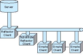
The PERIPHLEX architecture is built upon a central server which distributes data to multiple clients through a redistribution point referred as "reflector client". A second client is acting as a substitute distributor in cases where the main reflector wishes to leave, or is unable to continue supporting data distribution. The model is based on the architecture depicted in figure 1.
Figure 1: PERIPHLEX distribution model
In the case a unique client is connected to the server, there is no need for a reflector, but only when a second client near the first one connects to the server, the first client becomes a reflector. The reflector is responsible for redistributing the data it receives from the server in the scope of a limited area, defined in as "a cluster". By the term cluster we delineate the area within the limits of a LAN in which data transmission over multicast is supported. It is usually considered to be the area behind a router (where information is sent over a multicast address using IP packets with the TTL field set to 1). However, it may be a wider area (if the router enables distribution of data over this multicast address).
The server is the central point in charge of data distribution to the clients and of setting up the distribution network in terms of appointing reflector roles, assigning communication addresses for each distribution cluster, and even proposing reflectors to clients requesting data from the server. The server decides for data distribution to the clients by taking into account the available resources on its own side such as outgoing bandwidth availability and processor capacity. It maintains a list of connected clients that act as reflectors, together with a representation of the distribution scheme of these clients on the network. Finally, the server is administrating the handover/takeover procedures between a reflector and its substitute on the occasion the former is leaving the distribution chain or is unable to support the data redistribution process from the server to all neighboring clients.
Clients are the nodes in the network architecture that receive the data distributed by the server. Such a node may either simply accept the distributed data, or act as a reflector to the server, redistributing it to a local cluster through multicasting. Data redistribution is accomplished by unicast or multicast, based upon the existence of more than one client within a certain area that may or may not support IP multicasting. The area that supports IP multicast forms a redistribution cluster.
The simple client only receives the data distributed by the server. In cases when there is just one client connected to the server with no other clients in the vicinity of this client, there is no need for a reflector. However, this client is a candidate for becoming a reflector whenever other clients appear in the same cluster. In the normal case, whenever a new simple client requests a connection directly to the server, the latter upon acceptance of this request, notifies the client that is, from this point forward, a candidate reflector, with a specific Reflector ID (RID).
The reflector is a client that has been delegated the responsibility to distribute the data that receives from the server to all other clients within the same cluster. A reflector exists only if there are more clients in the same cluster area, and only for the period that these clients are active. In the occasion that only one client exists within a cluster, this particular client is a candidate reflector and is acting as a simple client receiving data from the server without retransmitting these data locally. Whenever another client appears in the same cluster then the candidate reflector will be upgraded to actual reflector. Finally, for each group of reflector and simple clients, only the reflector address is stored in the server together with a network topology including all available (actual and candidate) reflectors.
The substitute reflector is a simple client that has been designated as substitute reflector by a reflector client. This procedure takes place upon connection of the client to the reflector for receiving the distributed data. The specified client, apart from acting as an end-sink for the distributed data as every other simple client, is also constantly notified about the reflector's distribution parameters involving the rest served clients. On that ground, upon unavailability of the reflector (either normally or abnormally) and if it is necessary, the substitute reflector takes its role, and appoints a new substitute reflector.
The full distribution model used in PERIPHLEX is depicted in figure 2.
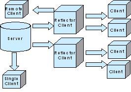
Figure 2: Distribution model
The notion behind PERIPHLEX is the selective use of unicast and multicast transmission for supporting data distribution to specific groups, using a central distribution server assisted by several peripheral reflectors. Owing to that, unicast transmission is used for delivering the data from the server to the reflectors, while from this point forward, multicasting at a local level is used for forwarding the information to all other clients. Unicast connections to the server are limited by the available server resources, and a decision for a new connection request is taken based on the availability of these resources and a maintained network architecture scheme on the server. In the event that a new connection request cannot be supported due to shortage of resources, the most suitable of the proposed redistribution points is selected from the requesting client. This point is a remote reflector which can be used by the client for receiving the transmitted data from the server indirectly. The difference from the normal case (a client is receiving data from a reflector within a cluster) is that data is now transmitted over a unicast connection instead of multicast.
The PERIPHLEX model uses several transmission methods for distributing the data covering both unicast and multicast transmission and utilizing both Transmission Control Protocol (TCP) and User Datagram Protocol (UDP). We may distinguish the following types of communication that take place between the elements of the PERIPHLEX architecture:
As shown in figure 3, the server (S) keeps a database with all the available reflectors (with clients A and C in the paradigm being already active reflectors). A new client N arrives and requests a connection to the server S. The server examines the requesting client's domain name and does a suffix match, in order to send to N the SRL containing potential remote reflectors A and C, together with a multicast address pair (data and control) in which the requested data stream may be transmitted within a cluster. N listens to the multicast control address assigned by the server for "alive messages" indicating the existence of a reflector within the same cluster. In the event of failure (implying that no local reflector is available), client will attempt to connect and start receiving data directly from the server.
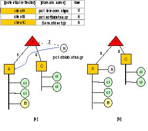
Figure 3: PERIPHLEX distribution model for a remote client
At this point, the server may accept or decline the direct connection based on available resources (i.e. processing power and available bandwidth). Either way, the client conducts an experiment to measure the available bandwidth between the alternative solutions N and C (and the server) to determine the most appropriate solution in terms of available bandwidth. The best solution for serving the requested data stream is chosen and the client connects to this "remote" reflector.
The aforementioned selection procedure of a remote reflector applies also when the client is directly connected to the server.
The model presented in this paper provides the platform for using multicasting and unicasting as the means for redistributing the information from the reflectors to the clients, based on network resources. The decision for the connection of each client to the most appropriate reflector is based on a probing mechanism that works in two steps: First it examines the availability of local distribution points, and if such a point is not found, advances to the selection of the most suitable distribution point (this being either the original server, or a remote reflector). This decision is taken from the client based on a proposed reflector list from the server. This list is proposed from the server based on a mechanism that examines the IP address of the client that requests connection to the server, and a DNS lookup mechanism for determining possible proximity of existing reflectors to the requesting client. This procedure takes place once upon client connection to a distribution source. However, during a session to the server, the distribution architecture may change due to the introduction and/or departure of reflectors. Therefore, the initial decision of the client for connection to a distribution point may no longer be optimal. For this, a supporting probing mechanism executed periodically at the server could be used, based on traceroute for determining the routes between the server and the reflectors. This mechanism used in conjunction with client IP inspection and DNS lookup could lead to a more accurate representation of the distribution mechanism in the server.